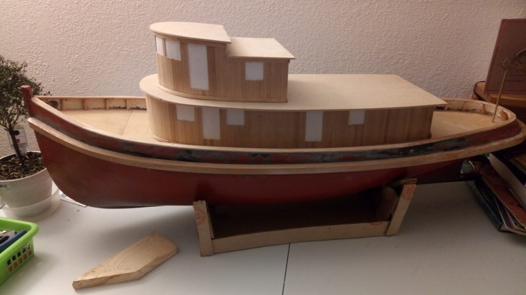
Very long overdue, but I have made a little progress. First an overall view.

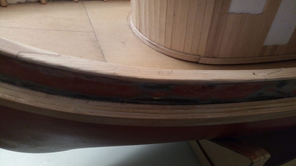
You can see here that the wheelhouse is attached to the top of the cabin structure. The roofs for the wheelhouse and the captain’s cabin are loose at present, I have put in a horizontal floor inside the wheelhouse and have paused to think about the wall, steps, and door between the wheelhouse and the cabin. Also showing are the rubbing strake, the bulwarks, and the cap rail on the bulwarks. Here’s a couple of closer views of them.

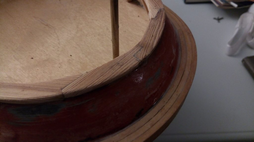
The Rubbing Strake is laminated from three layers of 1/8 in by 3/8 in fir, and the cap rail sections are carved from 1/8 in by 1 inch fir. Both are modelled on the Swell, in Victoria harbour, the lamination of the rubbing strake will be painted or stained to conceal it since the one on Swell looks to be solid timber. The joints in the cap rail are the same form as those on Swell, and I think I am going to keep that bright. Here’s how they look at the stern.

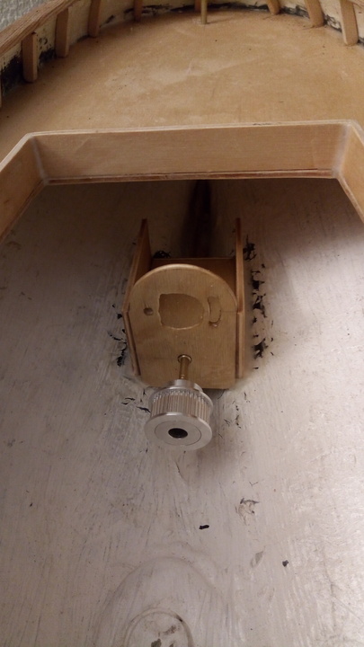
Finally, I have built the motor mount into the hull towards the stern. I am using a two to one reduction through a toothed belt drive, you can see the bottom pulley on the prop shaft at the bottom. The line-up is not so critical as a direct drive, but I think it is pretty close, there’s a second vertical plate at the back beyond the motor and whole shebang was built to be square with the prop shaft running through holes in the two plates. The motor will mount directly above the prop shaft, with the elongated hole on the left providing belt tension adjustment.

Because the prop shaft rises with respect to the hull, I was able to slide the motor mount sternwards , trimming the two side plates as I went to fit the hull before using epoxy to glue it in.
The motor is a 775, with a 12 volt battery, which should seriously overpower the tug, so I’m a little nervous about the strength of the mount.
Well, that’s where she’s at right now, more whenever I get some done.
Edward.
