
So now we have a complete hull, ready for a deck. I cut some deck beams to fit the top of each frame, about 1 inch wide and with the deck camber on top. After some fine tuning to get the sheer line right, I glued the deck beams to the frames. I like to mark the centreline on each beam – it helps keep things even later on when cutting some beams to accommodate the deck opening. You’ll have to use your imagination, since I forgot to take a picture.
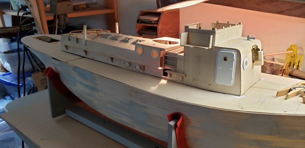
As you can see, I also built the superstructure – in two pieces – more about superstructure later.
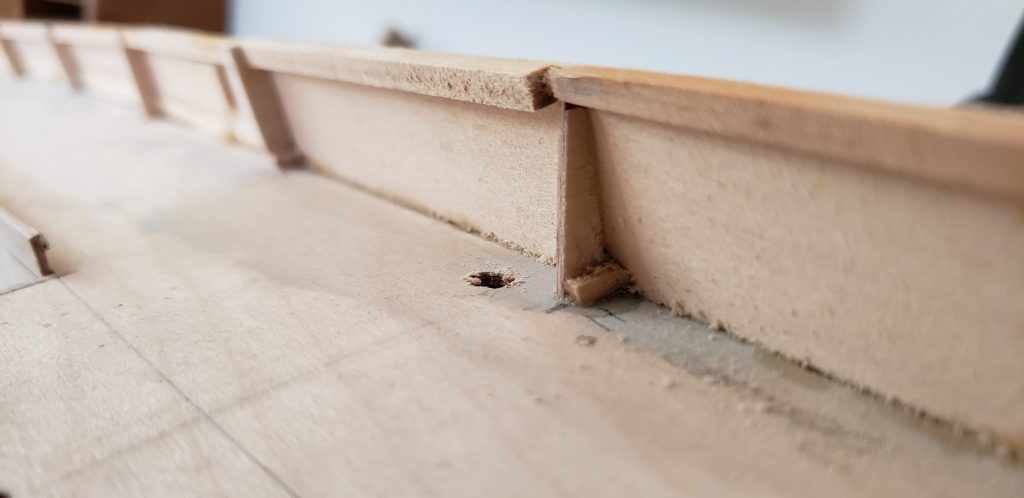
Once the deck was on and the hole cut for the superstructure, I was left to contemplate the bulwarks. I had planned to cut 1/16 basswood or ply to fit angle braces glued to the deck. But didn’t have enough material , there was Covid-19, I wanted to get it done, etc, etc. So I planked the bulwarks with whatever was at hand, and it seems to be ok. Some filling required.
The rubbing rail is two layers of 1/4 x 1/8 strip, which covers most of the wobbles along the join between bulwark, deck and hull. The bulwark will be topped with a mahogany top rail, so the filler strips at the top will be hidden – they provide a bigger surface for attaching the top rail.
I laid out all the deck fitting locations before attaching the deck – along with a centreline. It’s much easier than trying to do it after the deck is attached.
Next, the stern.. The shape of the curve at deck level was defined by the 1/16 deck -with the curve taken from plans – on top of the balsa blocks. I left the balsa blocks a bit proud, because I wasn’t sure how I would attach everything.
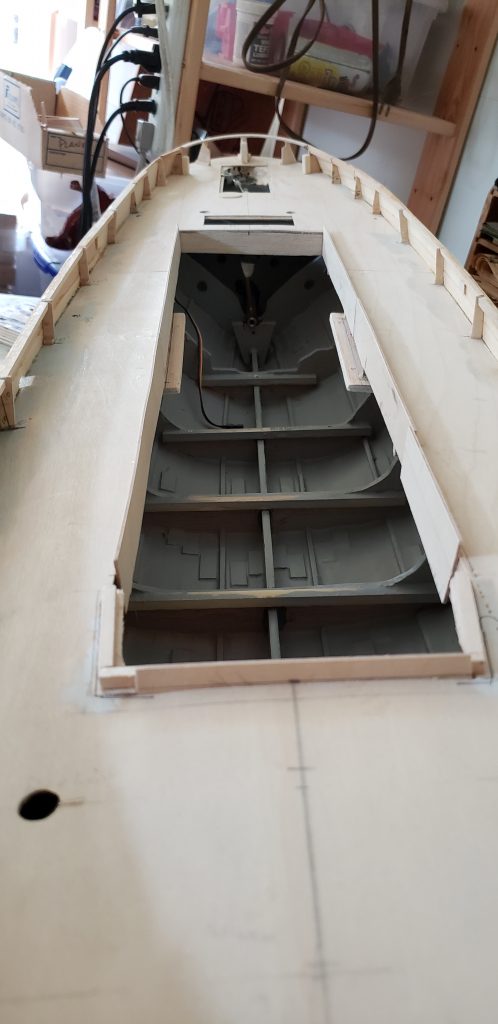
Cullamix has a raised grating over top the rudder post and a tiller arm, which is moved by chain and cable running along the inside of the bulwarks to the wheelhouse. There isn’t much room for a servo and linkage to the rudder post, so I moved the servo forward and angled the linkage up through the deck. It will be hidden under the raised grating, and still leaves room for the tiller arm and chain.
If I can resolve the connections to the wheelhouse, the bridge wheel will be turned by the rudder servo. We’ll see if it works.

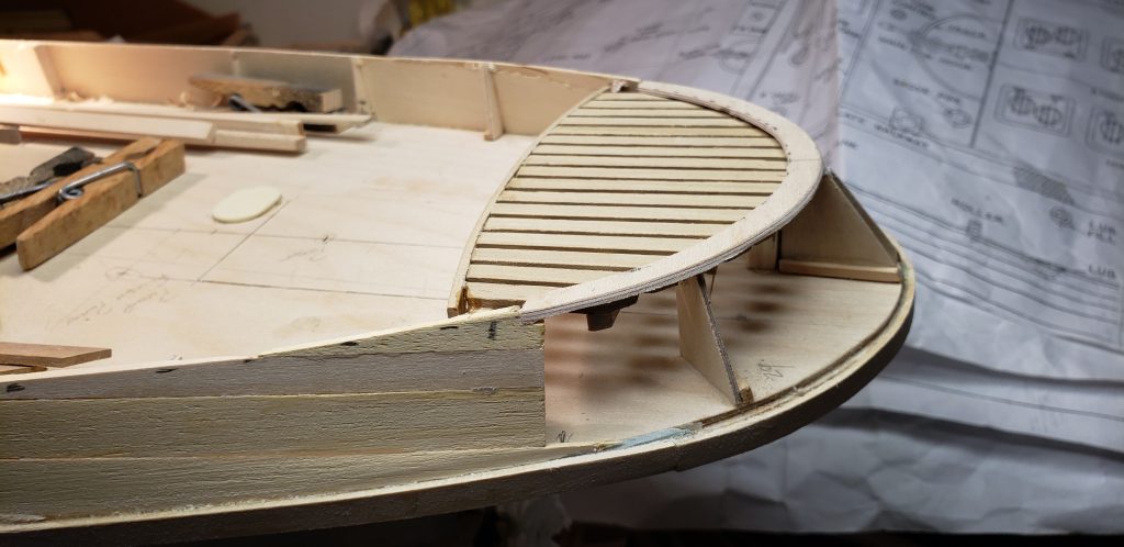
The gap around the stern will be covered with wide mahogany planks running from the rubbing rail up to the top rail. You may have noticed a deck opening just behind the engine room superstructure. I put that in to provide access the shaft coupler without having to remove the motor. Everything will come loose eventually, so you’ll need to be able to get at it!
The hull has now had two coats of polyurethane and is ready for primer and paint.
Superstructure is basically complete as well. I separated the wheelhouse from the engine room because I wanted to be able to lift off the engine room section for access to batteries and smoke generator, etc, without having to disconnect the tiller chains. The wheelhouse will also contain the sound system speaker – more wiring! This way, I can still have access to the front of the hull if needed without having to disconnect everything every time the smoke generator needs oil.
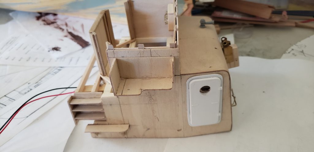
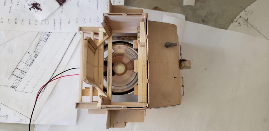
The wheelhouse has a nice wood grating for a deck, so should work well with the speaker. Sound is from an Mtroniks module with a Napier diesel.
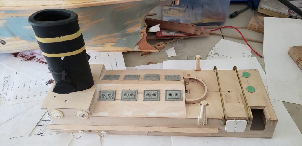
The engine room top pretty simple with a ply box and a styrene funnel. I didn’t make the funnel fold down – seemed like a lot of work for limited return. OK I’m lazy!
I still have to figure a robust connection between wheelhouse and engine room structures. There is a wooden slat walkway between the two that will have to stand up to some abuse each time the top is removed.
So it’s coming along. Next time I’ll show you the engine and electronics.